Anyone involved in 3D printing/additive manufacturing (AM) knows about STL file formats. Problem is – and no offense meant – STL is dumb. It’s just a large text file, generally written in ASCII programming language, defining the surface of a closed solid using a zillion triangles. For every tiny triangle the file lists Cartesian coordinates locating its three vertices plus a normal. You can slice it up to print, but that’s it.
STL files cannot include any information about desired color, desired material, surface texture, internal density gradient, internal fine structure, or other parameters that could be highly useful. So, some years ago several groups with smart, forward-thinking members began developing smart, forward-looking file formats for just this purpose. The two main versions are AMF and 3MF; this post will describe features of the 3D Modeling Format, 3MF.
 Logo for the 3MF Consortium, the industry group that is developing the 3MF file format for enhanced 3D printing. Image courtesy 3MF Consortium.
History/ Purpose of the 3MF Committee
In early 2015, Microsoft along with major corporations such as Autodesk, Dassault Systèmes, HP, Shapeways and SLM Solutions Group formed a consortium they named 3MF, with the goal of overhauling a little-used file format called 3D Modeling Format. (The consortium operates under the Joint Development Foundation.) Its goal has been to create a format that supports full-fidelity 3D models suitable for 3D printing and related processes while minimizing interoperability problems.According to the Microsoft 3MF documentation page, 3MF is “a set of conventions for using XML to describe the appearance and structure of 3D models for the purpose of manufacturing (3D printing).” In general terms, 3MF is designed to be complete, simple, extensible, unambiguous, human-readable and freely accessible with respect to royalties, patents and licensing. The group now comprises fourteen founding companies including 3D Systems, EOS, FIT AG, GE Global Research, Materialise, nTopology, PTC, Siemens PLM Software, Stratasys and Ultimaker; additional companies are involved as associates.
3MF Details and Specifications
Using common structures defined by Open Packaging Conventions (OPC) such as ZIP and XML to ease development, the group members initially created a core 3MF specification; several significant task-specific extensions have since followed. A helpful 3MF FAQ page presents answers to such questions as why isn’t 3MF binary and how does it compare to STL/OBJ/AMF/STEP/etc.A 3MF file holds metadata describing such basic information as the part title, designer and date of creation; mesh data – the body of 3D geometry constructed from a set of vertices, defined in a way that sets all face-normal vectors to face outward; data on base material groups and material types within those groups; data on color (without specifying a material); ways to define composites of materials (which types and in what ratio); data on texture and where to place it; information that maps materials to individual faces; ways to map the same component information to other sections of a part (saving file storage space); and slicing instructions that can be more accurate than sliced mesh data.
The 3MF extensions so far are: 3MF Materials and Properties Extension, 3MF Slice Extension, 3MF Production Extension, and 3MF Beam Lattice Extension. The latter was announced just this past April and provides an elegant non-hardware-specific solution to represent both small-scale lattices and larger truss structures – a key advancement for lightweighting.
All these details help software developers add the “Save as 3MF” option to 3D CAD software packages. On the other side of the equation, developers of 3D printer systems use the format to guide them in creating software for slicing and setting up prints, as well as directing the printer hardware to create parts with properties that can vary voxel by voxel.
Some Current 3MF Applications
Justin Kidder, director of graphics and software architecture at Dassault Systèmes SOLIDWORKS and a 3MF consortium representative, says the new data structure provides multiple benefits. “From the CAD perspective,” he says, “3MF files are significantly smaller than corresponding STL files. (They are also) a ‘container’ for 3D printing data, so CAD vendors can include other manufacturing or design history data into any 3MF file for downstream use.”Currently, when you save a SOLIDWORKS file as 3MF, in the Save As window, you can click on Options and choose whether to include materials and/or appearances (which includes color). More features will be coming, particularly since HP and Dassault Systèmes announced in February they would align their future technology roadmaps.
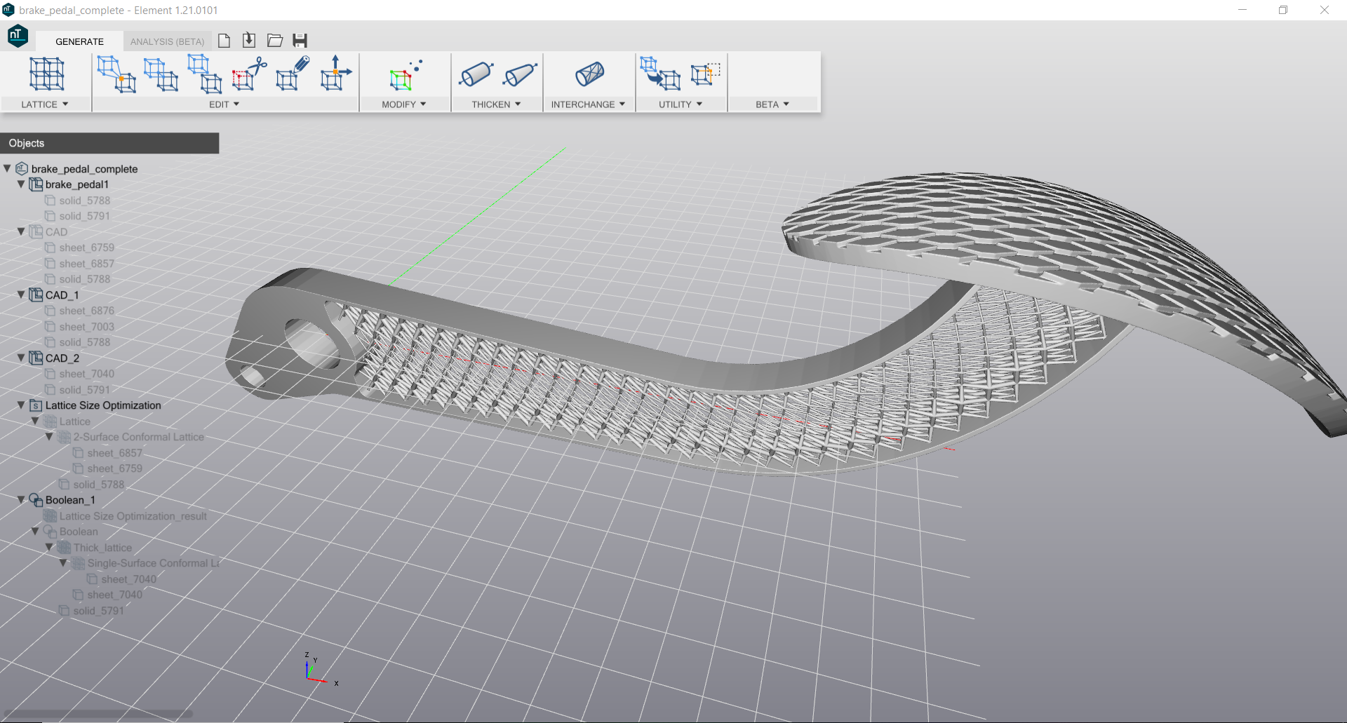
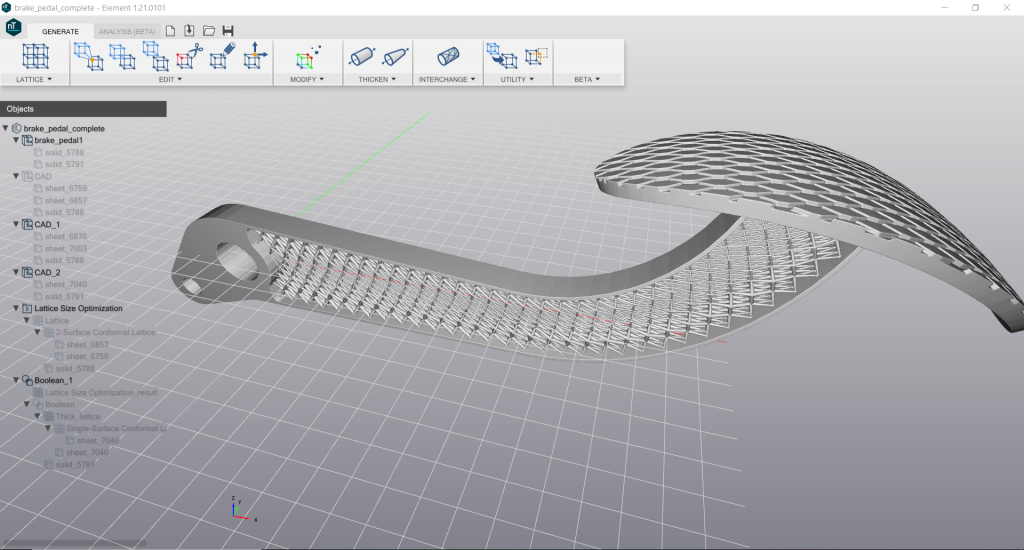 Internal lattice structure of a 3D printed brake pedal, designed with nTopology Element Pro software and saved as a 3MF file for intelligent 3D printing. Image courtesy nTopology.
Spencer Wright, another consortium representative who, among other jobs, coordinates partnerships and integrations at nTopology, explains that the 3MF Beam Lattice extension is key to any workflow that includes engineered lightweighting. “Lattice-specific software like nTopology Element Pro can enable big design improvements,” he notes, “but exporting those designs as STLs is cumbersome, resource intensive, and inflexible. 3MF’s Beam Lattice extension allows engineers to use the right tool for the job at every point in their workflow, and the file sizes are literally one one-thousandth what the corresponding STL would be.”
How to Add Color/Material Now, Without 3MF
Digitally Augmented Parts built on Rize One systems let users import files in STL, OBJ and several other formats and add text or images (such as QR codes). Rize Software lets users set up the build file to include printing text or images in and on any surface of the part; currently, single-color ink is offered. Step-by-step instructions are provided. Julie Reece, Rize VP of Marketing, says that 3MF files carry significant intelligence on the additive part that can now be carried directly from the digital world into the physical world using Rize’s new Digitally Augmented Parts capability.Printing on Stratasys PolyJet systems, such as the Objet500 Connex3 and higher models, means you can print in multiple materials and colors, blended from base materials and palettes that achieve as many as 500,000 unique colors. The proprietary system software walks you through steps that let you select surfaces, regions or sub-assemblies on the imported STL model and assign colors, digital materials, Shore-A hardness and more.
3D Systems offers several versions of its full-color-capable Color Jet Printer (CJP) line. Currently, when users import a polygonal model such as STL, OBJ, VRML 1/2, PLY, ZPR, ZBD, they can import color/texture information stored in or along with those formats, depending on the exact one used. They also can activate several tools in 3D Systems’ 3D Sprint part-preparation software to assign color to parts, regions or faces.
As more 3D printing equipment supports color, texture, multiple materials and other developments, 3MF will play a key role in simplifying the process for everyone.
About the Author
Press releases may be sent to them via [email protected]. Follow Robotics 24/7 on Facebook
Follow Robotics 24/7 on Linkedin
Article topics
Email Sign Up

